VXLAN allows us to create a logical topologies in the Data Center for our virtual machines. With VxLAN we are able to create a layer 2 network on top of layer 3 infrastructure. In the Data Centers VMs needs to be deployed in a specific segment of the network. These VMs can be moved from one host to another for maybe because of capacity problem or maybe host failure. In that case, It is clear that VM will keep its ip configuration, means it needs to be part of same broadcast domain even after it moved to another host which is probably connected to another access switch.
Fundamentally, VXLAN provides mechanisms to tunnel multiple layer 2 networks across a Layer 3 IP based infrastructure. The VXLAN base use case is to connect two or more layer three network domains and make them look like a common layer two domain. In the Data center environment this allows virtual machines on different networks to communicate as if they were in the same layer 2 subnet.
Edge devices are the most important part of VxLAN overlay. Edge devices are connected to underlay with and ip interface. They responsible from VxLAN encapsulation and decapsulation. VxLAN tunnels doesn’t have state information in the core. Only the edge devices will be aware of these tunnels.
VxLAN Encapsulation
VxLAN is basically MAC in UDP encapsulation.

VxLAN Header
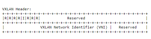
Flags: Only “I” bit of flags is set if the VNI is valid. All other bits are reserved for the feature.
VNI: The VNI tag is a 24bit field which gives us around 16 million tags. The VNI tag is kept inside VXLAN header while the packet is moving in the underlay. Two types of VNI’s are used which is one for L2 operations and one for L3 operations.
L2VNI is a direct link between laver 2 VNI and VLAN’s (dot1q) and it’s recommended to keep this one-to-one relation between L2VNI and VLAN’s.
L3VNI is a routed VNI which is used when traffic is moving between two different L3VNI (subnets), so this will have an IP associated which is used for routing purposes.
Reserved: There are 2 reserved bits; 8 bits and 24 bits. Both of the fields are set the 0.
Outer UDP Header
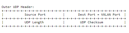
This is the outer UDP header with a source port provided by the VTEP and the destination port being a well-known UDP port which is 4789. The destination port can be changed with the configuration because some early implementations of VxLAN has different destination ports. When you need interoperability with these implementations you may need to change.
Source Port is calculated using a hash of fields from the inner packet. This fields is helpful when you have ECMP paths between source and destination VTEPs.
Outer IP Header
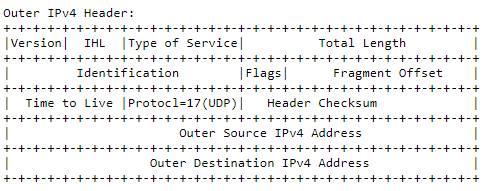
It has VTEP address of ingress and egress nodes as a source and destination ip address. Usually the destination address is unicast address. But there is also option to use multicast data plane for the BUM traffic. In that case the destination address will be a multicast address.
Outer Ethernet Header
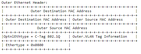
It has outgoing interface mac address as a source and next node’s mac address as a destination. Of course it will be changed hop by hop.