With the rapid evolution of SDN, industry have started to separate networks as Underlay and Overlay. An overlay is a virtual network that is built on top of an underlying network infrastructure, underlay. It is the underlying network responsibility to deliver packets across networks.
Here are summary of Underlay and its characteristics;
– Physical infrastructure which overlay network is built on.
– Related protocols are Ethernet switching and Routing.
– Responsible for packet delivery
Best solution for underlay is using IP based network with IGP or BGP.
For the IP address planning;
– Plan /31 addresses for the point to point interfaces, define your Spine-Leaf connection as route port.
– Plan /32 addresses for loopback interface, VTEPs will use loopback addresses as a source and destination address when encapsulating packets into VxLAN.

Using OSPF for Underlay Routing
– OSPF a widely adopted IGP that has been employed in many LAN, WAN, and data center core network environment.
– The OSPF default interface type used for Ethernet interfaces is “broadcast,” which inherently results in a designated router (DR) and/or backup designated router (BDR) election. Changing the interface type to point-to-point avoids the DR/BDR election process and, therefore, reduces the time required to bring up the OSPF adjacency between the leafs and spines.

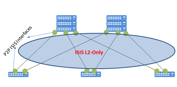
Using ISIS for Underlay Routing
– ISIS is another link-state routing protocol that also uses the SPF algorithm to calculate the shortest and loop-free paths through a network.
– IS-IS does not operate on the IP layer but instead resides at Layer 2, forming adjacencies using a connectionless network service (CLNS). It can transport any kind of addressing (IPv4 as well as IPv6) over the same routing exchange.
– In IS-IS, IP information is carried in a type-length-value (TLV). Because IP prefixes are always considered external, at the end of a shortest path tree calculation in this configuration, running a full SPF is not required when an IP network change occurs.
– P2P circuits are recommended.
– Implementing L2-Only can be helpful for future expansions.
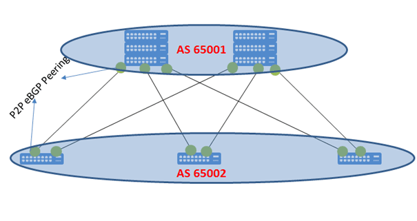
Using BGP for Underlay Routing
– BGP functions well in making routing decisions based on paths, network policies configured by a network engineer. While BGP is great for enforcing policies in a network, it was not specifically developed for fast convergence or link-path calculations.
– Best practice is using eBGP peerings over P2P interface ip addresses
– Consider the next hop ip address information. With eBGP, the next-hop attribute is always set, which means the neighbor of a route becomes the next hop. In the spine–leaf topology, this would be inappropriate. It can be optimized by setting eBGP the next-hop attribute to unchanged.
– It can be designed with 2 AS, where the Spines share one AS and Leafs share another AS.
– In the two-AS mode, some adjustments are needed due to the AS path violation that occurs when the source AS is the same as the destination AS. (You need to allow as-path loop)
– It can be designed with multi-AS. In the eBGP multi-AS model, all spines belong to one AS, and each leaf belongs to a unique AS.
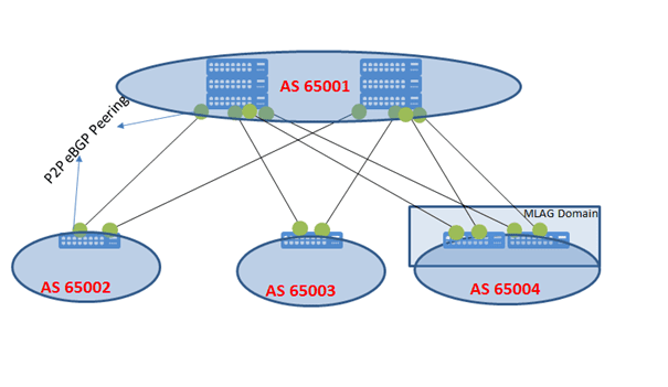
– With a single BGP instance per network switch, when using eBGP in the underlay, the overlay also needs to be configured in eBGP.
– iBGP also can be used with RR at the Spine Layer.