An SR Policy is used to instantiate an ordered list of segments. A Segment is and instruction that a node executes on the incoming packet; Forward packet according to the shortest path, Forward packet through a specific interface, Deliver packet to a given application or service etc. A Segment Identifier (SID) identifies a Segment. And the format of a SID depends on the implementation; MPLS Label or SRv6 Address.
If your path definition includes several segments, it can be encoded as a list of segment IDs. This SID List will be represented by an SR Policy. It is not same but similar to MPLS TE Tunnels. In MPLS TE, every tunnel will be represented with a MPLS label which will be pushed into the header. In every node along the path state information will be kept related to this very tunnel. With SR Policy, there will not be state information on transit nodes because all path information will be encoded as a SID list (Label Stack in the MPLS data plane and SRH header in the IPv6 Data plane) and pushed into the header. We will not have tunnel interface and we will not have state information on the transit nodes with SR Policy.
No Tunnel Interface
The question is, if there is no tunnel interface, how we will identify the SR Policy? Of course the SR Policy can have a name but every SR policy will be identified with tuple; Head-end, color and End-point. The Head-end is the node where the policy is implemented. It may be an IPv4 or IPv6 address. The End-point indicates the destination of the policy. The endpoint is specified as an IPv4 or IPv6 address. And the color is a 32-bit numerical value. Color can be used to indicate a certain treatment provided by an SR Policy.
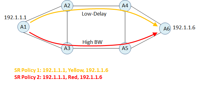
On one SR Policy can exist with a given color between 2 nodes. In the topology, I have 2 different policy which have different paths. Yellow policy takes the path with the Low Delay and Red Policy takes the path with high bandwidth. We didn’t see the inside of the SR Policy yet but as a first step I should say that, these paths can be defined as an explicit path or they can be dynamically calculated. We will come to this phase soon.
In one SR Policy you may have one or more candidate paths. An SR Policy will have one single path entry in the data plane which will be selected between candidate paths. A path is selected for an SR Policy when the path is valid and its preference is the best among all the candidate paths. According to current draft RFC highest preference value is the best. A head-end can learn about candidate paths for an SR Policy by local configuration, NETCONF, PCEP, or BGP. (In BGP we have new NLRI to signal SR Policy candidate paths)
How To Steer Traffic Into SR Policy
Steering with Binding SID
First method is using Binding SID (BSID). BSID is used to provide greater scalability. The BSID is bound to an SR Policy which may have a list of SIDs. Any packets received with an active segment equal to BSID are steered onto the bound SR Policy.
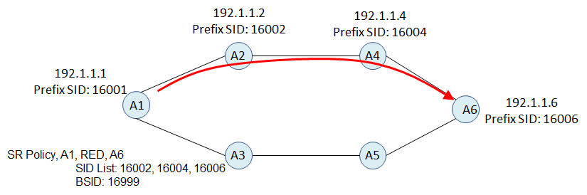
According to topology and SR Policy, SR forwarding table on A1 will be;
Incoming Active Segment: 16999

Operation: PUSH 16002,16004, 16006

Egress Interface: The interface towards to A2
If any packets from a client or application comes to A1 with an MPLS label 16999 (which is the BSID of an SR Policy Red) A1 will remove BSID and push the label stack which is s SID List of SR Policy. If it was IPv6 Data Plane, it would be an SRH with Segment Lists.
Automated Steering
Remember that every SR Policy is instantiated with a tuple and it includes a color. Color is a 32 bits value and it can be used with BGP as a “Color Extended Community” By default, if the BGP next-hop and color of a route match the SR Policy color, BGP will install the route with the related SR Policy. It may be an IPv4 or VPNv4 route. This can be assumed that it is one of the most important behavior of SR Policy.

According to topology and information in the topology;
- A6 sends and BGP Updated with a next hop itself and extended color community Red.
- A1 checks its SR Polices and it has an SR Policy A (A is the name of policy) with and head-end 192.1.1.6 and color Red. (Matches with BGP next hop and color)
- A1 installs the route into its fib with this SR Policy
Prefix: 29.8.140.0/24,

Next Hop: 192.1.1.6

SR Policy: A

Incoming Active Segment: 16999

Operation: PUSH 16002,16004, 16006

Egress Interface: The interface towards to A2
Usually we will defined one color for one BGP prefix. But in case of having multiple color in the BGP update, numerically highest color and its SR Policy will be used. If the highest color policy becomes invalid then the next one will be used.
In my opinion this is the most powerful feature of SR Policy. We can define any constraint with an SR Policy and Color. We can also add color extended community to out BGP updates. Constraint can be anything, it can be low cost, low delay, affinity, excluding some links etc.
Using Color Community
As a simple example see the below topology. SR Policy 1 and SR Policy 2 are defined on A1 and they have the colors of Yellow and Red respectively. There is a BGP session between A1 and A6, A6 sends some BGP updates with different colors. In this case 100.1.1.0/24 with an extended color community of Red and 200.1.1.0/24 with an extended color community of Yellow.
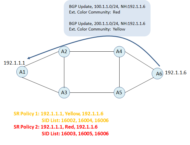
Forwarding table of A1 will include the following entries;
Prefix: 100.1.1.0/24,

Next Hop: 192.1.1.6

SR Policy: 2 (Red)

PUSH 16003,16005, 16006

Egress Interface: The interface towards to A3
Prefix: 200.1.1.0/24,

Next Hop: 192.1.1.6

SR Policy: 1 (Yellow)

PUSH 16002,16004, 16006

Egress Interface: The interface towards to A2
This behavior can be used with SRv6 also. In this example I assumed that color extended communities are added to BGP update on A6 with a route-policy. But it is also possible to add, remove or change the colors on ingress PE which is A1 in this example.
One other way of steering traffic into the SR Policy is using Policy based route.