SRv6 is a new source routing paradigm which means that the source can define the path that the packet will take. There are already some other ways to do this “Source Routing” but SRv6 is candidate to be easiest way. It is possible to run Segment Routing on MPLS Data and IPv6 Data plane. To understand the whole idea about SRv6 it’s better to visit IPv6 address and Extension Headers first.
In SRv6, we have an optional internet-layer information and it can be carried in separate headers called Extension Headers. Extension Headers may be placed between the IPv6 header and the upper- layer header in a packet. We have the “Next Header” field in the IPv6 header and every extension header is identified by a distinct Next Header value. I will not go through all kind of headers here but one of them us imported to us: Routing Header. This header is designed to be used for Source Routing with SRv6. Now it is improved to be used in the Segment Routing IPv6 Data Plane with a new type which is Segment Routing Header.
Comparision with MPLS Data Plane
I will go with the details but first let’s illustrate how this is going to work with a very simple example with both MPLS and IPv6 Data Plane.
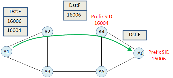
Assuming that we want to use Green path and we pushed SID list (16004, 16006) including the Prefix SID of A4 and A6 which is the final destination.
- A1 pushes SID List as a label stack
- A2 pops the outer label (Assumption is shortest path to A4 is over A2 and PHP is enabled)
- A4 pops te last label (PHP is enabled)
Now let’s change these prefix SIDs with IPv6 Addresses or SRv6 address with a better definition. And nodes have the Loopback IPv6 addreses defined as local SID. (Note that these are not actual headers, it is just forwarding logic)

Step by Step Explanation
- A1 pushes the header with 2 IPv6 address, 2981:40:A6::1 and 2981:40:A4::1 (Will be represented as Destination Address)
- A1 and A2 does IPv6 routing on based on Destination Address.
- A4 is the endpoint for the 2981:40:A4::1 and changes (NEXT) the Destination Address with 2981:40:A6::1
- A6 is the final destination and goes with upper layer.
It is not how exactly headers are working with SRv6 but the logic is very similar to MPLS data plane. In the MPLS data plane we have outer label and it may change along the path. But by default IPv6 data plane doesn’t have labels instead it has IPv6 Destination Address and it may change along the path. SRv6 is the option to achieve source routing and Segment List definition in theSegment Routing Header. Now let’s visit this header a little bit and demonstrate the same example with the real header information.
Segment Routing Header (SRH)
SRH is a new type of IPv6 Routing Extension Header and It may include a Segment List encoded as an IPv6 Address. Actually we should call these addresses as SRv6 addresses. Format is IPv6 address but in the Segment Routing model these addresses have 2 fields namely, Locator and Function.(And optional Arguments) There is no restriction about how many bits will be locator and how many bits will be function.
Locator: Routed to the node performing the function and it is like a network address. It is most significant bits of SRv6 address and used to route the segment to its parent node.
Function: Any possible function and every SRv6 address has it. There are several functions already defined for SRv6 and the simplest one is the END function. SRv6 END function and SR-MPLS NEXT operation are almost equal.
Arguments: optional argument bits to be used only by that SRv6 SID.
(According to draft RFC A function may require additional arguments and that would be placed immediately after the FUNCT. In such case, the SRv6 SID will have the form LOC:FUNCT:ARGS::. )
Here is the basic header with IPv6 and SR Header.
Segment Routing Header
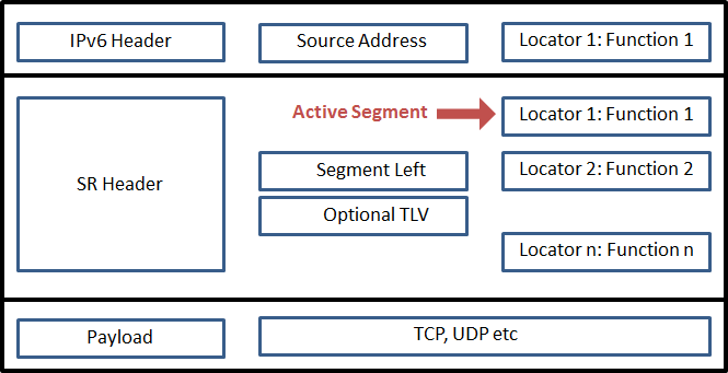
As you can see we have Segment List in the SRH and Active Segment is in the IPv6 header as a Destination Address. After a packet arrives to Locator 1, Function 1 will be executed and the next Segment from the list (which is Locator 2: Function 2) will become active. New Active Segment will be placed as a Destination address and Segment Left count will be decreased by 1. It will go on with same logic until the last Segment where the Segment Left will be equal to 0.
Original header according to RFC

SR Header (SRH) is created with Segment list in reversed order of the path. Segment List [ 0 ] is the Last segment and Segment List [ n-1 ] is the First segment. In the Source Node IPv6 DA is set to the first segment and Segments Left is set to n-1.
Most important part of this logic is Function. In this overview I will talk about END function but in the upcoming posts I will also introduce the other functions.
End Function
NH: Next Header,
SRH: Segment Routing Header,
SL: Segment Left,
DA: Destination Address.
END Function works as below;
IF NH=SRH and SL > 0
decrement SL
update the IPv6 DA with SRH[SL]
FIB lookup on the updated DA
forward accordingly to the matched entry
ELSE (SL=0)
Remove the IP and SR header
Process the payload:TCP/UDP
By default, End SID can’t be the last SID. If the SL=0 and packets will be dropped. Decapsulation of packet, removing the IP and SRH must be explicity defined in the End. My assumption is End SID is explicitly defined to remove SRH and process the payload at the end-point.
Now Let’s combine all these information in the first example withactual headers and tables.

Step by Ste Explanation
- A1, pushes SRH with 3 SID. From the SID list inside the SRH the first SID is copied into Destination Address field of IPv6 Header. Segment Left is set to 2. (n-1 where the n is total SID count)
- On A2, Destination Address of the packet is defined in the Local SID table with an END function. That’s why, A2 will decrease the Segment Left by one, the next SID from the list will be copied into Destination Address field of IPv6 Header and packet will be forwarded according to IPv6 routing table which is bound to incomin interface.
- On A4, Destination Address of the packet is defined in the Local SID table with an END function. That’s why, A4 will decrease the Segment Left by one, (Segment Left will be 0) the next SID from the list will be copied into Destination Address field of IPv6 Header and packet will be forwarded according to IPv6 routing table which is bound to incomin interface.
- On A6, Destination Address of the packet is defined in the Local SID table with an END function but Segment Left is 0. A6 will Remove the IP and SR header and process the payload.
In the same topology let’s assume we have one more node between A4 and A6 and it is not SR-Capable;

In this case, AX is non-SR node. It can not read nor process the SRH. But it is IPv6 capable and it will just forward packet according to Destination address of the packet and its routing table. We have 3 types of node in SRv6.
Source SR Node:
A SRv6 Source SR Node is any node that originates an IPv6 packet with a segment in the destination address of the IPv6 header. In the Source Node SRH is created with Segment List in reversed order. SegmenList 0 is the last, Segment List 2 is the first segment in our example. In our example A1 is Source SR Node where the destination address is set to first segment.
Transit Node:
A SRv6 transit node is where the destination address of that packet packet is not a local SID or local interface ip address. Transit node just need to be able to forward IPv6 packet but no need to do SRH inspection or update will be done on this node. In our example AX is Transit Node because the it doesn’t have any local sid which is in SRH.
SR Segment Endpoint Node:
A SRv6 endpoint node is any node receiving an IPv6 packet where the destination address of that packet is Local SID or local interface ip address. In our example A2, A4 and A6 are SR Segment Endpoint Nodes. A6 is the final destination and Final destination may or not may not be SR-capable.
(Local ipv6 addresses including loopback interface address are not local SID by default and they need to be configured as local SID. And Local SIDs don’t have to be associated with an interface)
ECMP Between Segments
If there are several paths and some of the has equal cost towards to Destination Address, load will be shared.

According to topology and SID list in the SRH, between A2 and A5 load will be shared. A3 and A4 will continue to forward the packet based on their forwarding table. They will not do SRH inspection and update in the header.