The distributed IP anycast gateway applies the anycast network concept“one to the nearest association.” Anycast is a network addressing and routing implementation in which the data traffic from an endpoint is routed topologically to the closest node in a group of gateways. The function of the Anycast Layer 3 gateway is natively embedded with the BGP EVPN control plane. With VxLAN/EVPN implementation there are as many Anycast L3 gateways as Top-of-Rack switches.
The EVPN introduced the concept of Integrated Routing and Bridging based on EVPN to address inter-subnet communication between VMs which are belong to different VxLAN segments. It is also called inter-VxLAN routing.
Let’s see how is IRB is working with the topology.
Each VTEP learns through the data plane and registers its local end-points with their respective MAC and IP address information. Every VTEP distributes this information through the MP-BGP EVPN control plane.
We can assume following entries will be installed for VTEP-1 as an example. Other VTEPs will have similar entries of course. (note that these are not actual outputs but summary of what is included in the outputs)
VTEP-1
VM1, IP: 10.100.1.1, MAC: MAC-VM1, Vlan:100, L2VNI:298100, Next Hop: Local
VM3, IP: 10.100.1.3, MAC: MAC-VM3, Vlan:100, L2VNI:298100, Next Hop: 192.1.1.2
VM2, IP: 10.200.1.1, MAC: MAC-VM2, Vlan:100, L2VNI:298200, Next Hop: Local
VM5, IP: 10.200.1.2, MAC: MAC-VM5, Vlan:200, L2VNI:298200, Next Hop: 192.1.1.3
VM4, IP: 10.30.1.1, MAC: MAC-VM4, Vlan:300, L2VNI:298300, Next Hop: 192.1.1.2
VM6, IP: 10.30.1.2, MAC: MAC-VM6, Vlan:300, L2VNI:298300, Next Hop: 192.1.1.3
VM7, IP: 10.30.1.3, MAC: MAC-VM7, Vlan:300, L2VNI:298300, Next Hop: 192.1.1.4
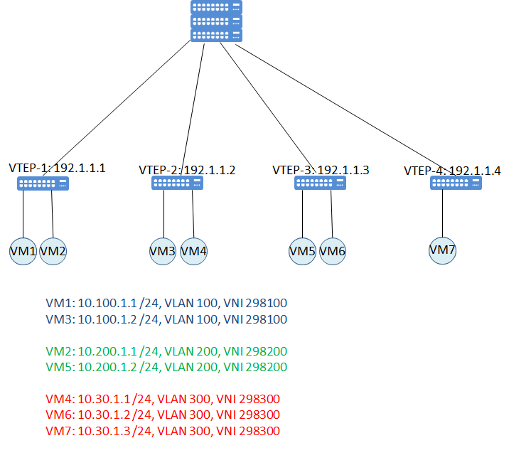
We will have following VxLAN networks;

Let’s assume all networks are belong to same tenant and all gateways are configured on all VTEPs.
Step by step communication between VM1 and VM4 as an example;
- VM1 sends packet to VM4. Layer 2 destination mac address is VTEP-1 which is the gateway of VM1. VTEP-1 decapsulates the packet and performs the routing.
2. VTEP-1 routes packet to the SVI 30. Because the destination ip address of the packet is in the same subnet with SVI20.
VM4, IP: 10.30.1.1, MAC: MAC-VM4, Vlan:300, L2VNI:298300, Next Hop: 192.1.1.2
3. VTEP-1 encapsulates packet into VxLAN with the VNI 298300 and sends it to the VTEP-2. (This is called asymmetrical routing mode and with asymmetrical routing mode, the ingress VTEP performs both bridging and routing)
4. VTEP-2 receives the packet strips off the VxLAN header and bridges the frame to its VLAN 30 which is mapped to VNI 298300. (The egress VTEP performs only bridging.)
VM4, IP: 10.30.1.1, MAC: MAC-VM4, Vlan:300, L2VNI:298300, Next Hop: Local
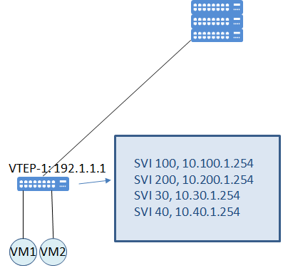
The drawback of this asymmetric routing (Asymmetric IRB) implementation is the we need to be sure about consistent configuration across all VTEPs. All VTEPs shoud have the configuration of all VLANs and VNIs which will be routed or bridged between VTEPS.
In the above illustration, VTEP 1 needs to be configured with VLAN 100 mapping VNI 298100, as well as the VLAN IDs which are mapped to the VNI 298300, even though there is no any host attached to this VLAN. Note that the VLAN ID being local significant. In my example I used consistent Vlans but what is critical is that the mapping to the true VNI. Therefore, in this example the Host tables on all leafs are populated with the reachability information for VM1, VM2, VM3, VM4, VM5, VM6 and VM7.
In the asymmetric IRB we only have the concept of L2VNI. We also have another option which is called Symmetric IRB and it introduces us with the concept of L3VNI. This L3VNI will allow us to create and dedicate VRF for a specific tenant for the routing purpose.