No additional signaling or state is required in order to provide interworking in the direction LDP to SR. A SR node having LDP neighbors can create LDP bindings for each Prefix-SID learned in the SR domain by treating SR learned labels as if they were learned through an LDP neighbor.
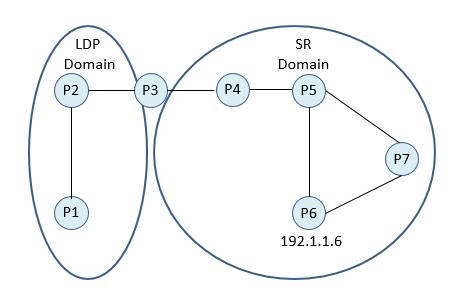
According to topology, P1 and P2 are running pure LDP, P3 is running both LDP and SR and P4, P5, P6 and P7 are running pure SR. From the IGP perspective all nodes are in the same domain.
Prefix SID for P6 is assigned as 16006 and it is distributed in SR domain.
In LDP domain also some MPLS labels are dynamically assigned for ip prefix 192.1.1.6/32. P3 node has both LDP and SR binding for 192.1.1.6/32.
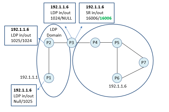
For the prefix 192.1.1.6/32, In the forwarding plane of P1 LDP mapping is
Incoming LDP Label: NULL
Operation: PUSH 1025 (Allocated by LDP)
Egress Interface: The interface towards to P2
For the prefix 192.1.1.6/32, In the forwarding plane of P2 LDP mapping is
Incoming LDP Label: 1025
Operation: SWAP 1024 (Allocated by LDP)
Egress Interface: The interface towards to P3
For the prefix 192.1.1.6/32, In the forwarding plane of P3 LDP mapping is
Incoming LDP Label: 1024
Operation: POP (End of LDP Domain, PHP is disabled)
Meantime we will have following entries SR forwarding plane of P3
Incoming Active Segment: NULL
Operation: PUSH 16006 (Prefix SID of P6)
Egress Interface: The interface towards to P4.
In the data plane, it will work as following;
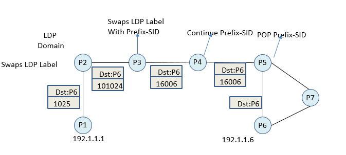
- P1 pushes LDP Label (1025)
- P2 Swaps LDP label (1024) according to its ldp table
- P3 Pops LDP label and Pushes Prefix-SID. (According to RFC, P3 automatically created forwarding entry with and incoming label 1024i operation swap, outgoing label 16006)
- P4 continue with the prefix SID
- P5 pops the prefix-SID (PHP)
It make sense to have MPLS tunnel from LDP Domain to SR Domain because of interconnecting router that is P3 in this case. But for MPLS tunnel from SR Domain to LDP domain, we will need more. In the same topology, if we want to have SR tunnel to node P1, somehow we need to have Prefix-SID of P1 in our SR domain. This can be achieved my Segment Routing Mapping Server (SRMS).
SRMS simply creates and advertises Prefix-SIDs for the prefixes which are out of our SR Domain.
Here are some notes for Segment Routing Mapping Server.
– Enable SR-capable nodes to interwork with (non-SR-capable) LDP nodes.
– Mapping server is a control plane mechanism, that’s why it does not have to be in the data path. You can think like a route reflector.
IS-IS advertises prefix-to-SID mappings in the SID/Label Binding TLV. Each block of prefix-to-SID mappings is encoded in a separate TLV
OSPF advertises prefix-to-SID mappings in an Extended Prefix (type 7) Opaque LSAs. In the Extended Prefix Opaque LSA, the prefix-to-sid mappings are encoded in OSPF Extended Prefix Range TLV.
– Mapping server must be resilient. It is suggested to use at least 2 mapping server. When multiple Mapping Servers are active, it is necessary that the information advertised by different mapping servers should be consistent.
– Mapping Server has a Client-Server architect. If a mapping server is used, all other nodes should be mapping client to receive mapping entries about Non-SR nodes. Note that, client will accept these entries if the prefix is installed to their link state database.
– Mapping Server function is implemented in the link-state protocol like OSPF and ISIS. According to latest drafts Link-state protocols allow propagation of updates across area boundaries. Mapping Server advertisements are propagated through the usual inter-area advertisement procedures.
Let’s return back to same topology and assume we have configured;

P7 is SRMS and all other SR nodes are configured as SRMS-Client. In that case after running SPF and installing 192.1.1.1/32 into their ip forwarding table, all nodes also will install prefix-SID of P1 into their SR forwarding table. From to P3 perspective it will have both MPLS LDP label mapping and SR Prefix-SID for 192.1.1.1/32.
In P3 we will have following entry;
Incoming Active Segment: 16001
Operation: SWAP with LDP Label
Egress Interface: The interface towards to P2.

- P6 pushes 16001 Prefix-SID of P1 (which is configured on SRMS)
- P5 Continues with 16001
- P4 Continues with 16001 (PHP disabled)
- P3 swaps Prefix-SID with LDP label (1045)
- P2 swaps the LDP label
In summary; The Mapping Server function of a SR capable router allows distribution of mappings for prefixes not locally attached to the advertising router. This allows advertisement of mappings on behalf of non-SR capable routers. The Mapping Server is a control plane only function which may be located anywhere in the IGP flooding scope. Multiple Mapping Servers may be present in the same network for redundancy.
It is also possible to have LDP, SR and MPLS TE together in whole network as a part of migration strategy. On the PE nodes, you can decide which tunnel to be used; SR, LDP or MPLS TE.