In today’s network, path control can be achieved with MPLS Traffic Engineering tunnels. These tunnels can be created with protocols like RSVP-TE and CR-LDP. Even for the SR-MPLS and SRv6. When defining paths, both static and dynamic options are available. MPLS TE is deployed today by many operators to optimize network bandwidth usage, to provide strict QoS guarantees, and to ensure sub-50ms recovery in case of link and node failure.
But MPLS TE usage is currently limited to a single IGP area/domain. Because basically, IGP hierarchy limits topology visibility to Ingress LSRs and Ingress LSRs can’t run CSPF to calculate shortest path.
One of the possible solution is using centralized controller by running is PCE (Path Computation Element). It can be used to compute MPLS-TE paths within a domain or across multiple domains and deliver it to the PCCs (Path Computation Clients) via PCEP.
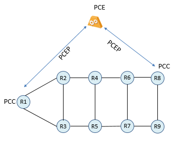
PCE Solution is an entity that is capable of computing a network path or route based on a network graph and applying computational constraints.
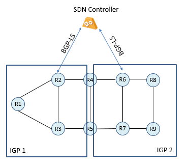
For the purpose of this solution, the whole topology should be visible to PCE or an SDN Controller even in a Multi Area or Multi Process IGP design. SDN Controller can run ISIS or OSPF to get LSDB and TEDB information from the routers including SR Prefix SIDs and Adjacency SIDs. IGPs are very chatty, so the controller will spend too much time for processing all these chatty updates. In the cases where the network consists of multiple IGP domains, then it could be a challenging on where to place the SDN Controller which peers with IGP.
Or an alternative approach can be, Link-State Distribution using BGP.
There is a growing interest in getting an abstracted view of the entire network so that higher level applications can provide useful functionalities to businesses. Applications like PCE can use such information on a real time basis to enable administrators to plan and optimize the network usage. PCE can be used for calculating optimal paths for TE in an Intra-Area and Inter-Area TE deployment and it requires complete topology information including Traffic Engineering database.
The link-state and TE information can be collected from networks and shared with external components using the BGP routing protocol. This is achieved using a new BGP Network Layer Reachability Information (NLRI) encoding format; BGP-LS.
BGP-LS peering between Controller and a Node in the network, gives Controller topology information and TE parameters of each link. Including IGP metric, TE Metric, Administrative Groups, SRLGs etc.
BGP-LS specification contains two parts: new BGP NLRI and new BGP path attribute. Each Link-State NLRI describes either a node, link or a prefix. The BGP-LS attribute is used to carry link, node, and prefix parameters and attributes. And it is an optional, non-transitive BGP attribute.
Main source for the BGP LS database is IGP. Simply you can distribute link state and TE database of IGP into BGP and share with BGP peers like SDN Controller. BGP-LS support both ISIS and OSPF (v2/v3).
In order for two BGP speakers to exchange Link-State and TE Database, they must use AFI 16388 / SAFI 71 (SAFI 72 for VPN Links) capability codes when advertising BGP Capabilities. To ensure that they are both capable of properly processing such NLRI.
There 3 types of NLRI and 3 Types of LS-Attribute. These attributes are Optional non-transitive.
Node NLRI and Node Attributes,
Link NLRI and Link Attributes,
Prefix NLRI and Prefix Attributes. (Prefix NLRI can also be IPv6 Prefix).
Node and Link objects can be used to construct a topology info and IP Prefix object will provide IP reachability information.
For detailed information about NLRIs and Attributes please see the RFC 7752; https://tools.ietf.org/html/rfc7752

Only one of the devices needs to have BGP-LS peering with the controller. Similar to Figure 2, to improve reliability, deploying BGP-LS on two or more devices are recommended. The BGP-LS devices collect the same topology information, and they back up each other in case one of them fails.
Only one of the devices from every IGP domain needs to have BGP-LS peering with the controller. The BGP-LS devices collect the different topology information related with any IGP Domain and construct all network topology in order to create end-to-end MPLS Tunnels.
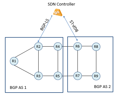
The topology information collected in AS 1 is different from that collected in AS 2. To address this problem, enable BGP-LS on at least one device (two or more is recommended for higher reliability) in each AS and establish a BGP-LS peer relationship between each of the devices and the controller.
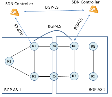
In order to provide Controller Reliability 2 or more SDN Controller can be installed. If two controllers are deployed which are connected to different Ass, a BGP-LS peer relationship must be established between the two controllers. So that both controllers can obtain topology information on the whole network.
In case of using SDN Controller to achieve end-to-end MPLS TE Tunnel deployment in same or in different domains, BGP-LS can be used to collect topology information.